CNHL Lipo Batteries
CNHL aim at providing high-quality Li-Po batteries and RC products to all hobby enthusiasts with excellent customer services and competitive prices
When Lipo battery is coated and dried, the adhesive will migrate to the surface due to capillary force, and as the coating speed of Lipo battery increases and the thickness of the coating increases, the migration of the adhesive will become more serious during the drying process, which will further weaken the dressing and the collection. The adhesion between fluids has a negative impact on the performance of Lipo battery. In order to solve this problem, Lipo battery double-layer coating technology came into being. Through multi-layer coating, the primer is compensated with a high ratio of SBR.
In the study, by combining two Lipo battery slurries with different SBR contents, the slurry with gradient SBR binder was double-coated. All Lipo battery electrodes consist of copper foil with a bottom layer of 50% thickness and a top layer of 50% thickness, three two-layer configurations (A+A, B1+B2 and C1+C2), at the same time, with the respective slurries A single-layer Lipo battery electrode was prepared as a comparative reference.
For the Lipo battery double-layer coating process, there may be three problems: (1) air infiltration; (2) longitudinal streaks; (3) mixing of upper and lower layers. Next, CNHL lipos, the manufacturer of Lipo battery, will introduce the content of Lipo battery coating in detail.
To study the stability of Lipo battery coatings, each coating condition of Lipo battery with different coating speeds and wet film thicknesses was evaluated and classified into three categories: no defect, lower limit, and upper limit. The area between the defect-free coating and the defective coating is called the coating window.
1) Different coating speeds of Lipo battery
Coating stability at 127μm gap between coating back rolls: At 0.5m/min, the minimum wet film thickness for defect stable coating is 87μm, when the speed is increased to 20m/min, the thickness increases to 90μm, at 1m/min peak value.
2) Different wet film thickness of Lipo battery
At 0.5m/min, the maximum wet film thickness before bulge expansion was 147μm, which decreased to 133μm at 20m/min. Defects are in the stable coating region between the stability limits and wet film thickness can vary without defect coating defects. No mixing of layers occurs between these stability limits. It can be seen that the minimum wet film thickness of the defective double-layer film is higher than that of the single layer, at a coating speed of 20 m/min, the single layer is 64 μm and the double layer is 90 μm.
When the larger gap is 420 μm, the lower limit of Lipo battery defect wet film thickness is 300 μm. The upper limit of wet film thickness is 510 μm at 0.5 m/min and 450 μm at 20 m/min. The minimum wet film thickness of Lipo battery double layer wet film is also significantly higher than that of single layer. This is caused by flow conditions in the upstream meniscus. If a Couette flow forms in the gap without the superposition of Poiseuille flow, the simulated pressure balance is approximately balanced.
This is the case when the Lipo battery wet film thickness is half the gap of the single layer coating. For the bilayer coating, 50% of the corresponding wet film thickness was decisive in this study.
In the case of the Lipo battery double-layer slot die, this flow is different from the flow in the single-layer slot die, where two fluid flows are created due to the two feed ports of the double-layer slot die.
For Lipo battery stabilizing coatings with minimum wet film thickness, Couette and Poi cloud flow are superimposed in multiple layers, resulting in higher Lipo battery wet film thickness.
In addition to the proposed failure modes of Lipo battery air entrainment and swelling, there are also two-layer mixed coating defects of Lipo battery. The UV-active markers were visualized by the proposed experimental setup and one layer of mixing (a mixture of two layers, the bottom layer of Lipo battery was blue with UV tracer, and the top layer of Lipo battery was unpigmented black, which can be detected optically)
The experimentally determined mixing process point is below the minimum wet film thickness of air infiltration, therefore, only at very low Lipo battery coating speeds of 0.2 and 0.5 m/min, the failure mode of Lipo battery mixing can be observed. No mixing was detected at coating speeds above 1 m/min and above the minimum wet film thickness. Mixing is caused by backflow within the coated beads and the resulting intense vortexing.
The literature indicates that the Lipo battery failure mode occurs when the layer thickness of the primer is less than one third of the back-roll gap. For the Lipo battery coatings used in this study, the top coat and base coat thickness ratios were 50%, which resulted in a critical bottom layer thickness well below the minimum wet film thickness in the relevant speed range, so the Lipo battery compound was outside the process window of this experiment.
The peel strength of Lipo battery can well characterize the bonding effect between the foil and the dressing, and can also indirectly observe the migration of the adhesive. Adhesion under different formulations of Lipo battery base coat and top coat: The adhesion is mainly determined by the SBR content near the collection foil, the greater the ratio, the greater the adhesion.
By doubling the SBR content directly on the Lipo battery foil, the adhesion also increased approximately twofold, from 23 N/m for 3.7 wt% SBR to 44 N/m for a single layer of 7.4 wt% SBR. This is evident in both single and double layers of Lipo battery.
Adhesion with a uniform distribution of binder for a single-layer coating is as high as that for a two-layer coating. For Lipo battery bilayer coating, the base coat has the same binder content as the single coat, while the top coat has much less binder, B1 (SBR 4.97%) 1+B2 (SBR 2.49%) The adhesion of C1 (SBR 7.46%) + C2 (SBR 0%) increased by 43.5% relative to A (SBR 3.73%). Therefore, Lipo battery-coated electrodes with SBR binder gradients can significantly reduce the total binder content without any negative impact on adhesion.
When the rate is lower than 1C, there is no difference in the capacity of single-layer coating and double-layer coating. At higher rates, the Lipo battery with double-layer coating can release higher capacity, and C1+C2 has the highest capacity at high rates. . In terms of cycle performance, at 1200 cycles, the remaining capacity of A+A is 87.7%, that of B1+B2 is 87.6%, and that of C1+C2 is 89.1%.
The higher adhesion of Lipo battery multilayer electrodes contributes to long-term stability. Compared with the single-layer coating, the Lipo battery two-layer electrode has a higher discharge capacity up to 11.0%, and shows slightly better results in terms of cycle performance.
The above is the whole content of Lipo battery coating brought to you by Lipo battery manufacturers. I hope this article will help you learn more about Lipo battery. For more information on lithium batteries, please read the following:
1s lipo battery design N/P ratio
What is the key problem with the super fast charging of the power 2s lipo battery?
CNHL aim at providing high-quality Li-Po batteries and RC products to all hobby enthusiasts with excellent customer services and competitive prices
Quick Fit Check The 2 Packs CNHL Black Series V2.0 1300mAh 22.2V 6S 130C LiPo Battery with XT60 Plug is a strong fit for FPV pilots who want a prov...
View full detailsHstar D43-01Q 911 Style is a mini 1/43 alloy drift RC car designed for indoor tabletop fun and realistic drifting. It features full proportional ...
View full details

Spare Parts Availability We know that for RC pilots, reliable spare parts support often determines how long an aircraft can actually sta...
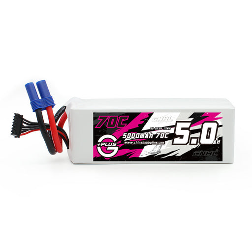
View full detailsSpecifications: Stock Number: 500706EC5 Capacity: 5000mAh Voltage: 22.2V / 6-Cell / 6S1P Discharge Rate: 70C Continual / 140C Burst Charge Rate: ...
View full details
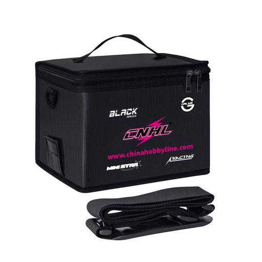
The CNHL LiPo Battery Bag is designed for safer LiPo charging, transport, and storage at home or at the field. It adds a practical layer of protect...
View full details

The Scania S730 Official Licensed 1/64 Mini Drift RC Tractor Trailer brings scale truck collecting and RC driving into one compact desktop model...
View full details

The Hstar D24-03S is a 1:24 Porsche 911 GT3 RS style 4WD gyro drift RC car built for indoor drifting, smooth-floor practice, and small home t...
View full details

The Hstar D24-04S is a 1:24 Toyota GR Yaris style 4WD gyro drift RC car built for indoor drifting, smooth-floor practice, and compact home tra...
View full details

The Hstar D24-01S is a 1:24 Toyota GR Supra style 4WD gyro drift RC car built for indoor drifting, smooth-floor practice, and small home tracks. ...
View full details

Quick Fit Check The 2 Packs CNHL Black Series V2.0 1300mAh 8S 130C LiPo Battery with XT60 Plug is built for advanced FPV pilots who want a comp...
View full details


Leave a comment